![[PukiWiki]](../../image/pukiwiki.png "[PukiWiki]")
|
Top > JANOG31 Programs > JANOG31_Network JANOG31 Networks in the venueOverviewJANOG network team provides various networks to JANOG31 visitors in the Tokyo Midtown Hall that can accommodate nearly 800 people, which include one stable network, five experimental networks, one network for staff. We will explain how to design and build its network, general considerations, methodology and experience of network construction in the JANOG31. Also, we will explain the experience of JANOG30 at Kurashiki Geibun-kan.  Table of Contents
RemarksThe IP addresses in this document and the configurations are temporary allocated from GREE, Inc for JANOG31 conference network. The addresses are no longer used for JANOG. Venue Tokyo Midtown Hall, the venue of JANOG31 is an urban multi-purpose convention hall for business. It has excellent building facilities, such as electrical facilities and information facilities. Thus, construction of the networks itself was easy. At the same time, the design team had to consider about the trade-off between use of existing infrastructure and the conference network.  Kurashiki Geibun-Kan, the venue used for JANOG30 is a theatre that are designed for orchestras and theater troupes. The venue was not intended to provide the information infrastructure by design. As a result, the team was laying network from scratch and struggled with many restrictions on its facilities. ConceptFirst of all, JANOG LA team needs have the concept of the conference network. The network construction process didn't go according to the plan. The team needs to change the original plan flexibly because of a deployment of the technology which is related to the program and the limitation in the equipments. Finally, the team provides six networks includes experimental network. JANOG provides two networks as minimum level; the stable network (includes wired connectivity to exhibitors) and the network for staff. In addition to that, Local arrangement team (LA) constructs the network as they want. For example, IPoE, Wireless network on 5GHz (802.11a) and network that uses 1.0.0.0/8 were provided in the past. In JANOG31, the team provided network: Interoperability test network of three vendor's 4rd implementations and the LISP network under its theme - "IPv4 over IPv6". The results were the publish an interoperability test result as an Internet-Draft, and establishment of JANOG Softwire WG (Working Group). One of the LA's mission in JANOG31 is "Provide the network that gave feedback to JANOG and the Internet industry". We break down the mission into three metric.
From this phase, we will determine network specification while negotiates with equipment contributors. Finally, we decided to provide three networks with new technologies: MAP-E, DS-Lite and 464 XLAT, and its theme is "IPv4/IPv6 transition and coexistence technologies". Also, we decided to provide HANA with NICT under the theme of "Oncoming generation network". Deployment of HANA was proposed by NICT in the wake of JANOG/IA (Institute of Electronics, Information and Communication Engineers's Technical Committee on Internet Architecture) collaboration event. There was another proposal that the network related to a GeoIP technology, but the proposal was abandoned since there is a risk of arbitrary change the location information of a particular IP address. So they decided to provide DS-Lite as an one of "IPv4/IPv6 transition and coexistence technologies" since the deployment of MAP-E and 464XLAT were already fixed. Prior to the event, we provided 2.4GHz (802.11bgn) as a default such as "janog30" and "janog30-a" for stable networks. From this time, we changed to 5GHz (802.11an) as a default such as "janog31" and "janog31-bg" . Because many equipments supports 5 GHz band have become popular. According to the above, JANOG31 team was decided to construct a following six networks. The design process started in August, and the final design was fixed on November.
Preliminary inspectionPreliminary inspection of the venue is also important. We confirm following points at the inspection. It is smoother if we have a plan of the venue in advance, so that we can design the network roughly.
upstream internet connectionCheck how the upstream internet connection is being provided at the venue. In the JANOG31 venue, there were 3 x B-FLETS, with YAMAHA CPE. However we arranged another CPEs and replaced existing YAMAHA CPEs with them, because YAMAHA was configured to serve only 50 clients with DHCP. In addition, we should arrange another ISP connection other than existing one because the venue did not disclose PPPoE authentication account information. In JANOG30, because there was no existing network connection in the venue, the meeting host deployed a dark fiber to their data center. This was possible because the host was local CATV operator, it was quite a special case. Location of the equipmentsAs for location, it is important to check whether we may place the equipments (such as a wireless AP) in the passage from the Fire Services Act point of view. If we plan to place equipments on the table we need to check whether it is required to protect the table. It is easy to use anti-static mats or bubble cushioning (it is better to do even it is not required). Location will also depend on the entry of equipment operators and power capacity. Two rooms were available in JANOG31 venue. In a room called the "control room", there was upstream connection and patch panel to each room. But we JANOG staff could not freely enter this room because it was used by the venue staff. There was another room that is away from the control room. Since it had a UTP wiring from the control room and JANOG staff could use it 24 hours, we decided to use it as a "NOC". It was required to protect the desk surface, which was put in each room. Wireless AP was likely able to be fixed to fittings. In JANOG30, we used sides of the stage as equipment storage. We need to put L2 switches on the floor in various places inside the venue for the wireless AP installation and sponsor booth. There were 2 tables in the equipment storage and we had to place all the equipments on them. So we had to fix the leg of the tables to prevent from collapse with equipments' weight. We put the wireless AP on the music stand for the score. Power CapacityPower capacity is very important. We have to see what Voltage and what Amp. is supplied from all electrical outlet. Circuit breaker trips if over-power the capacity of the venue. We have to adjust it to fit the power supply capacity range of venue. Expansion of the power supply might be available by venue, but since it will cost additional fee we should avoid it. In JANOG 31 venue we could use a wall outlet 15A circuit and two 15A circuit in the NOC room. We decided to use two 15A-circuit two systems for our equipments, and adjusted the placement of equipments to fit within 30A. In JANOG30, we had to put the transmission equipments from the host, we had used an additional 20A power supply on stage side. Cable RoutingWe calculate the length and number of the cables and the number of switches required, while verifying the wiring route. There is a machine that can be used to measure the distance with the infrared, you can measure the distance quickly. It is important to obtain the venue plan in advance and assume the cable route. We should not exceed the 100m in the UTP cable length. If a cable spans across the passage, we will need to confirm if we have to fix it by any means and/or protect it with a mat. Since it could wire to all the necessary rooms from patch panel in the control room in JANOG31, we just prepared many short cables such as 3 meter to 5 meter. However we had to make an application to use the pit for wiring to the hall center. In JANOG30 it was very hard because we had to lay the cables in both inside and outside in the hall. In addition, there was wiring across the passage, prohibited to use fix tape for wooden parts, vertical wiring to the second floor and 90m of cabling at the longest. We were very careful about these points. Because of them we had to change cable route several times and arranged cable protection mat for passage crossing. It takes long time to pull out if wire length is long. Radio wave condition of wireless LANIt is essential to check the wireless LAN usage for the provide stable wireless connection. Recent conference halls provides the public wireless LAN service so that many channels of radio may be useed. However, it does not matter if the utilization is low. We can visualize it with a software such as inSSIDer and / or airport in Mac. We can see traffic volume if we use an expensive WLAN analyzer. In JANOG31 venue, all channels were filled up to 5GHz from 2.4GHz for the public wireless LAN service provided by the venue, but traffic was very low. The venue staff said they had provided WLAN in the past for few hundreds of people, we had determined there would be no problem. In JANOG30, radio wave is not out in the venue, radio condition was very clean. Equipment ArrangementBased on the network design and physical design from preliminary inspection we arranged required equipments. Things to keep in mind with borrowing equipments are:
We need to make an agreement in advance the scope of responsibility for failure or lost during usage and/or transportation. In addition, since the borrowed equipments are transported from vendor -> hot stage venue -> meeting venue -> vendor, we have to decide how to transport them and who pays the transportation cost in advance. IOU is exchanged between the vendors and the responsible person. Arrangement of core network equipmentsFollowing is the network equipment to fill the minimum requirements.
How many wireless APs do we need? It depends on the size of the venue, but maybe from 12 to 15. Required number of L2 switch ports can be fixed aloing with it as well. Prepare PoE supported switches if possible. The reason is, 1) it can supply power the wireless AP by UTP cable, even the AP location is away from the outlet, 2) it is easy to pulling out the equipments after the conference (reduction of man-hours is possible). And, since several hundreds of clients connect to the internet at the same time in JANOG meetings, high performance is required for the upstream router (e.g. the number of NAPT sessions et cetera). Followings are optional: they will required if we monitor / measure at the venue or deploying separate (experimental) networks.
After we had identified the necessary equipments from the design, we looked for the vendors who can help us (providing equipments). It is difficult part, we called out to sponsors, or meeting staff arrange them by themselves. Hot StageGrand DesignL0/L1 DesignWireless DesignL2 DesignL2 design was done based on the network grand design and the structural requirements of the venue.
To do
Point to note
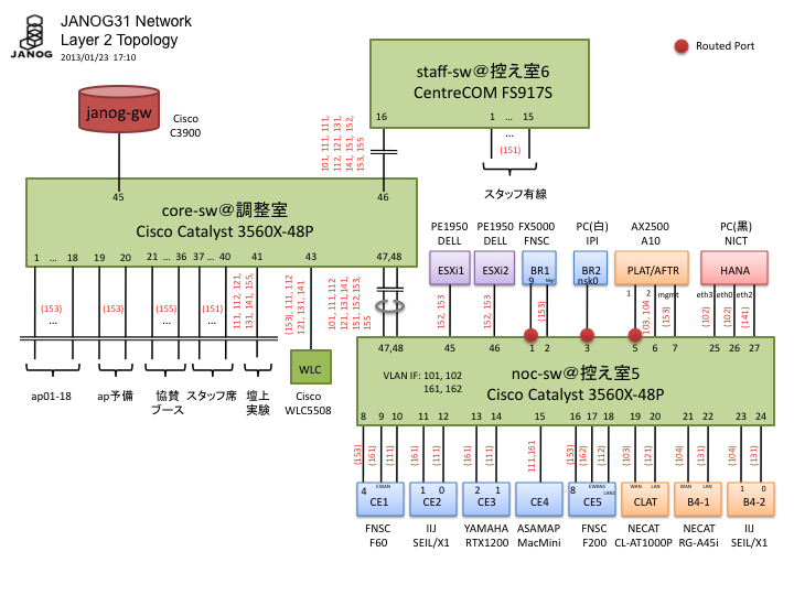
L2 design includes physical switch configuration, port assignment and VLAN assignment. L2 design is often constrained by physical limitations such as the location of switches and the specification of loaner devices. In order to make network compact, most devices are connected to L2 switches and segment those devices into VLANs. VLAN assignments depends on L3 design. First decided to deploy 48 port L2 PoE switch in Coordination Room and 48 port L3 swtich in NOC. The number of port needed was decided based on the number of devices to be connected. Deploying PoE switch is very helpful not only to make network topology simple but also to simplify network operation. Secondly assigned switch ports to all devices. Two ports were assigned to routers, one for LAN and another for external connection. In some case third port was assigned for management. It is recommended to assign ports based on physical location of each device without considering logical meaning of each port. VLAN assignment should follow some rule and be related to L3 address assignment. Refer the network diagram in the following “L3 Design” section for actual VLAN assignment. Assignment to physical ports is written in red in the L2 design diagram above. Numbers in parentheses describes untagged VLAN. At JANOG30 10 switches had to be spread all over the venue and VLAN assignment was written on a piece of paper , and the paper was attached ot each switch. But no such things were needed and L2 diagram was referred as all network devices could be connected to two switches. In case using cheap and/or old management switch, caution is advised that VLAN ID beyond 1005 is called Extended-range VLAN and can’t be used. If allowed it is recommended to assign VLAN ID between 1 to 1001. Other points to exercise caution are that treatment of VLAN1, or default VLAN, can be different per switch and that VLAN ID 1002 to 1005 are dedicated to Token Ring and FDDI on Cisco switches. It is advised that the use of VLAN trunking should be minimized and use physical port as much as possible. The reason being that port counters can be used and gives precise data when measuring traffic by SNMP for each experimental network. At JANOG31 Softwire WG demonstrated MAP-E BR failover, and it required BR to be connected to a routed port, or SVI of VLAN with only one port. Upstream port of AFTR/PALT for DS-Lite/464XLAT was also connected to routed port. Because of the requirement from L3 design, VLAN interfaces are configured to run the switches as router. L3 Design
To do
Point to note
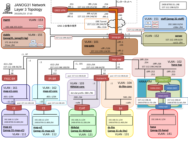
L3 design includes IP address assignment and routing design. Address space usable in the venue is limited, so efficient address assignment is required. Because the stability of the core network was priority on JANOG31 network, stable wireless users were directly connected to gateway router while all experimental networks were connected to L3 switches to isolate them. The usable address space for the venue was /23 for IPv4 and /48 for IPv6. IPv4 /24 could barely serve the experimental networks, /23 was allocated just in case. Upstream point-to-point segments and core network consumed the half of the entire address space and the experimental networks consumed another half. IP address is assigned based on rules as much as the address space allows. The address assignment on JANOG31 was not a good exaple in this regard. IPv6 has wider address space and VLAN ID can be embedded in IPv6 address. Other rules includes that making the numerical order of address matches to the physical order of the network and that devicesdevices in uppersteam in a segment has lower address and higher address for downstream devices. Easy-to-remember address assignment helps to avoid unnecessary confusion on installation and on troubleshooting. Static routing is used in this size of network. When using static routing, special caution needs to be exercised to avoid “ping-pong”. For example, in case that 192.0.2.0/24 is routed from an upstream router to a downstream router and that the downstream router uses a partial segment of the address space such as 192.0.2.128/25, if default gateway of the downstream is pointing to the upstream router, a packet destined to 192.0.2.1 goes back and forth between the two routers until its TTL expires. In order to avoid this “ping-pong” from happening, address space delegated to a router should be directed to null interface with the lowers administrative distance (:254). #Upstream router
ip route 192.0.2.0 255.255.255.0 203.0.113.2
# Downstream router
ip route 0.0.0.0 0.0.0.0 203.0.113.1
ip route 192.0.2.0 255.255.255.0 Null 0 254
NAPT design is included in L3 design. Session overflow could happen on NAPT to which many uses connect. During installation of JANOG31 network, only 20 staff members caused session overflow on NAPT. Two possible ways to solve this problem are to increase the number of external addresses and to reduce the session time by “ip nat translation *-timeout” or such. External ConnectivityCore RoutersCore SwitchesExperimental RoutersServersMAP-E Experimental NetworkDS-Lite Experimental Network464XLAT Experimental NetworkHANA Experimental Network |
|
|
Modified by janog i18n team.
Powered by PukiWiki Plus! HTML convert time to 0.301 sec. |